Miffy Mic
Update on making a custom miniature wireless microphone
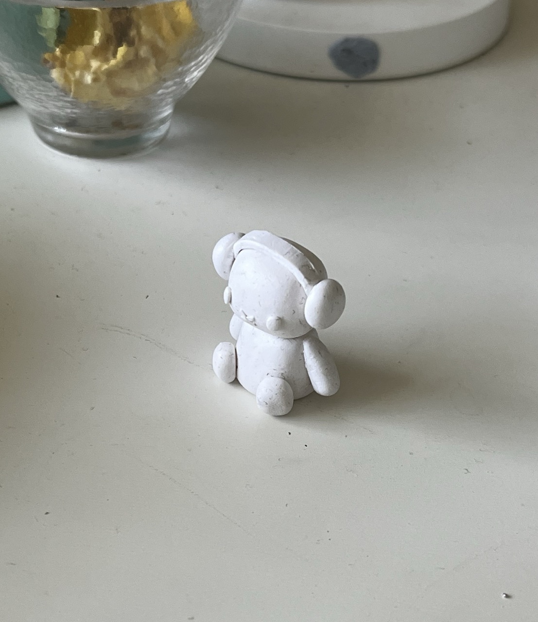
The aim of this project was simply to make the smallest possible wireless microphone with the materials I have. The size was constrained solely by the size of the miffy figure I wanted to enclose it in.
Research
Being a “smart” wireless microphone, the majority of the chip would be taken up by the microprocessor. Thus to make this project work, the first priority was to find a suitable sized Bluetooth/2.4GHz enabled chip that could be hand-soldered (too broke to afford a reflow kit 😔). After some scouring, I landed on the Feasycom BT634, for which at its insanely small footprint of 10x11.9mm had all the capabilities that were needed.
The microphone ended up being a MEMS microphone (to save on size), which would pair up nicely with the processor.
Given that the chip was so small though, it didn’t have the capabities of larger wireless modules like the SEEED Xiao, and thus components such as charging chips and voltage regulators had to be factored in too.
Schematic & PCB
Here’s the final schematic:
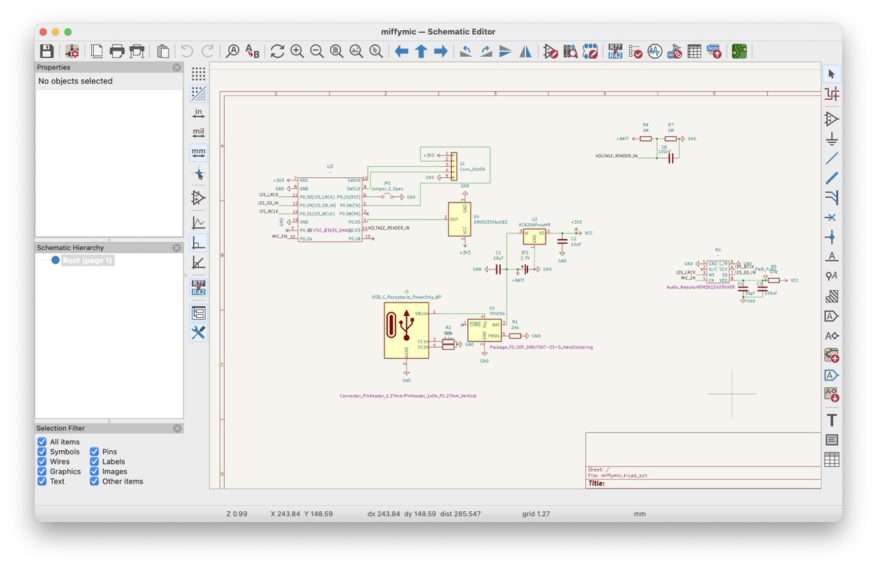
On the right hand side sits the microphone module, connected through a low-pass filter to prevent voltage spikes (driven by the BT634’s sending radio packets) from reaching the module. In the middle sits the charging circuit, consisting of the USB-C port, a TP4054 charging chip, and a Low Quiescent Qurrent (low current leakage to maximise battery life) XC6206 voltage regulator. On the left hand side is the BT634 (used a bt630 footprint cs its the same and im lazy), connected to the aformentioned modules. Thus this represents a complete chip, somewhat emulating the functionality of a SEEED Xiao in a much slimmer footprint (almost 2x reduction in width, but slightly longer).
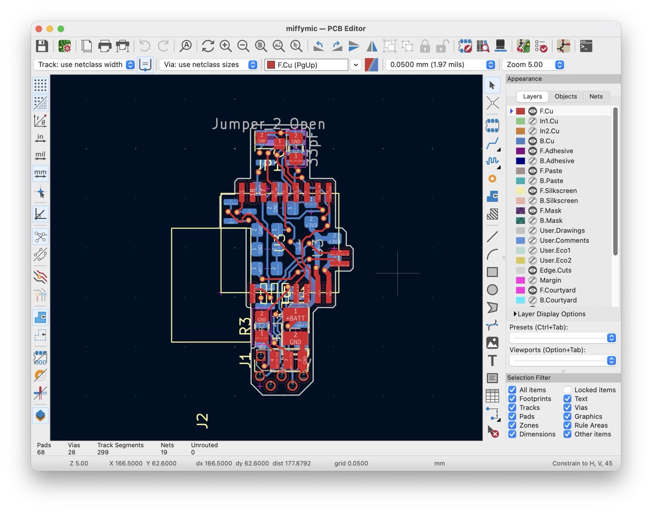
With about 3 hours of routing and rerouting, I was quite proud of the final PCB. It manages to squeeze ~8 or 9 fatass 0805 components onto the chip, which in hindsight might’ve been easier to just use 0603 ones. It utilises a four layer design, which helps minimise the electrical interference from the BT634 reaching the MEMS microphone on the other side by shoving two layers of copper between them (an active 3V3 layer and GND layer). These layers also helped with routing convenience!
Assembly
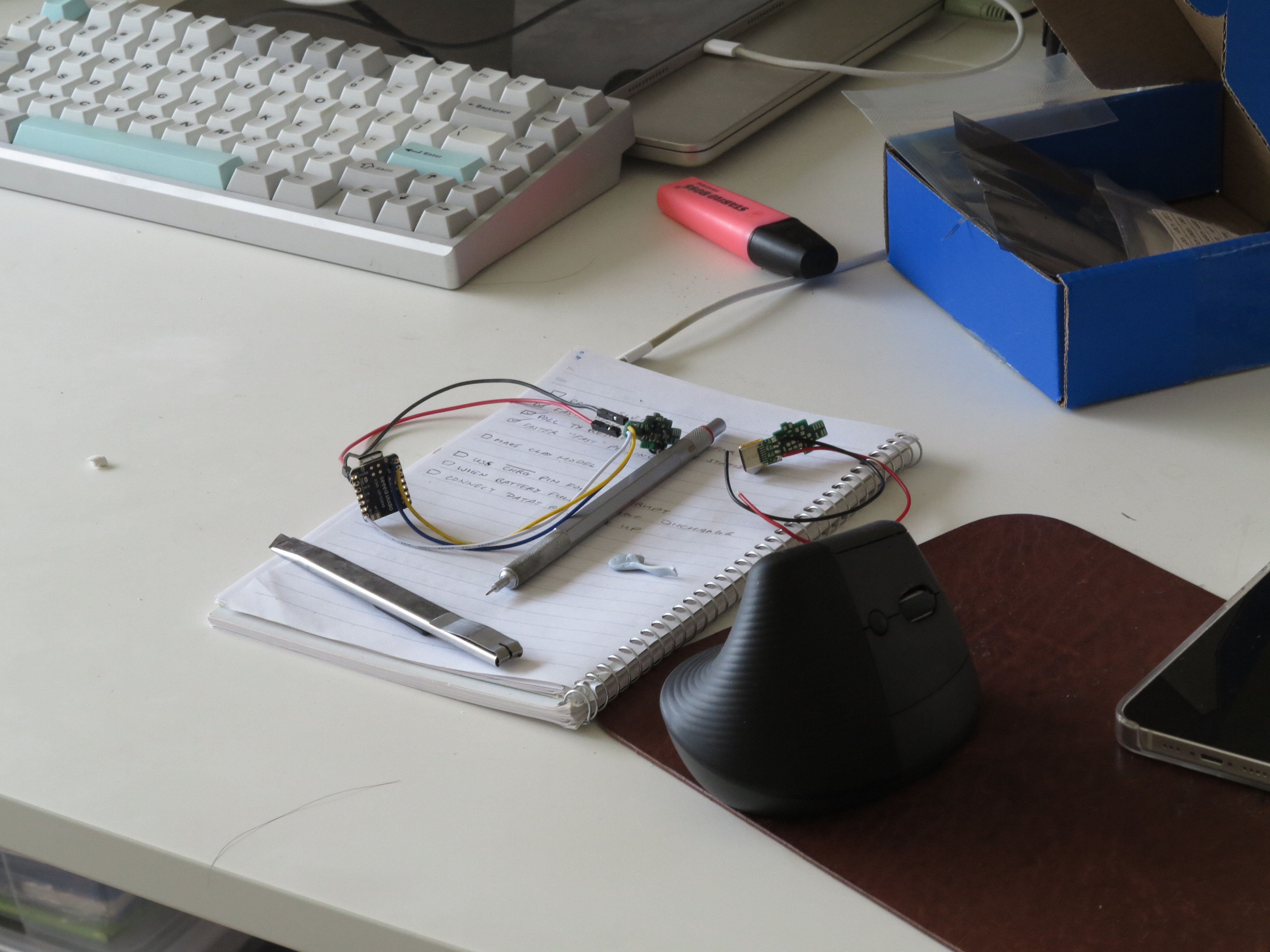
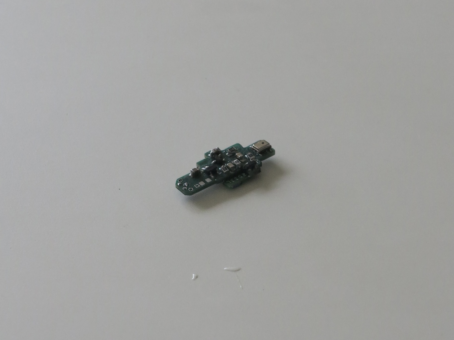
This is the prototype board that was assembled to test all the components, and thankfully I didn’t require a second shipment from JLC.
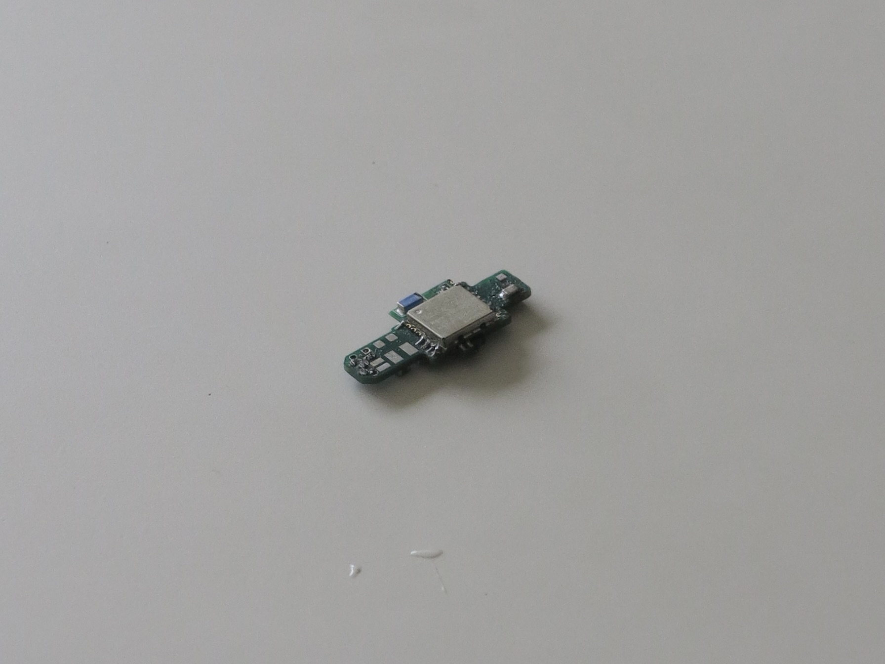
On the image below this, you can spot the MEMS microphone at the top, as well as the TP4054 and the XC6206. Plus the various fat capacitors and resistors. This is the last time you’ll ever see any semblance of good quality soldering, appreciate it while it lasts 😔
Software
It’s worth noting that the BT634 comes flashed with factory firmware that is unusable, and there is a specific process to reflash it such that it can be reprogrammed. In any case, I’m gonna write the steps here:
- You’ll need a seperate chip to flash this one. I used a SEEED Xiao. Flash that chip with a DAPLink programmer, and connect it to the BT634’s exposed progamming pads (SWDIO and SWCLK).
- run
openocd -f interface/cmsis-dap.cfg -f target/nrf52.cfg -c "init; nrf52_recover; exit", or a pyocd equivalent. - You should see something like
nRF52 device was successfully erased and unlocked. - If that doesn’t happen, and it says it can’t lock on or no ack, you may need to hold the RESET pin low/high to allow it to flash.
Once the BT634 is unlocked, it can take binary files and be flashed like any other chip.
The software runs on the the NRF Connect SDK, specifically the Gazell link layer. This is because the heart of the BT634 actually runs with an nrf52840 (manufactured probably by nordic semiconductor), which is programmable with NRF software, exposing functions like nrf_gzll_add_packet_to_tx_fifo() to allow you to interact with the BT634 radio using your code.
It’s not worth going too deep into the code logic, but when the recording mode is activated, it streams microphone data into the BT634, which uses an ADPCM algorithm (extremely lightweight to run, lossless and a 4x compression ratio) to compress the audio data so it may be sent over the air to the reciever. The receiver, a SEEED Xiao (as it doesn’t have size constraints like the miffy transmitter does), decodes the ADPCM data and streams it to the phone/ipad/mac over USB.
Final comments
Sadly I forgot to get any pictures of the final product as I ended up giving it to a friend, but it worked reasonably well within limits. I could have ordered a nicer microphone than the one I got, and the range of the BT634 was a bit lackluster, quite a lot worse than advertised. However, given that this project had a single prototype and had such strict parameters, I was still quite happy with it.